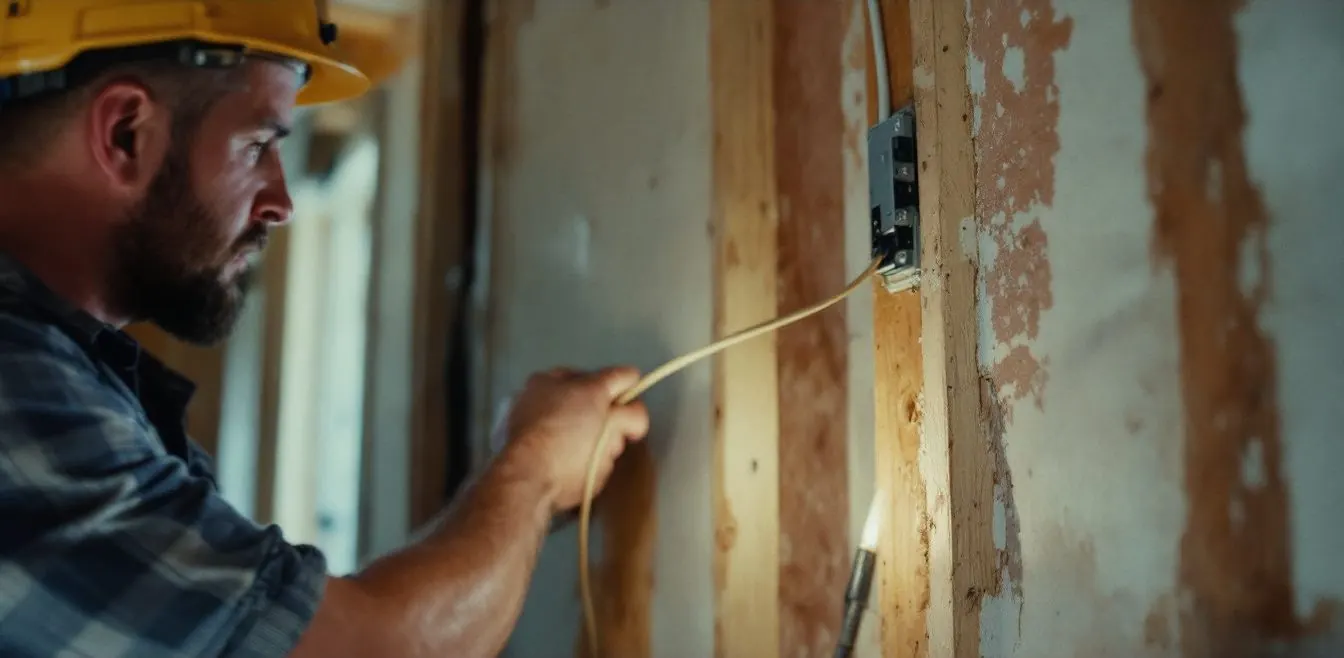
Yes, you can run thermostat wire next to electrical wire when the power conductors are inside Romex, armored cable or conduit; NEC 725.136(I) then sets no minimum gap. You cannot put Class 2 thermostat cable inside the same conduit, cable or box as line voltage without a barrier or a listed exception.
Which thermostat wire routes pass the code, situation by situation?
Touching a sheathed cable is fine; sharing its enclosure is not. The table applies NEC 2008 Article 725 and 2012 IRC Chapter 43, the newest editions we could read in full. Your inspector has the final say; this is not legal advice.
| Situation | Verdict | Clause | What decides it |
|---|---|---|---|
| Beside or crossing Romex, conduit or armored cable, touching or not | Allowed | 725.136(I)(1); IRC E4304.2 | Power in a cable or raceway waives the 2 in. rule |
| Through one bored hole with Romex | No clause bars it; inspector’s call | 725.136(A); 300.4(A)(1) | Not on the list in (A). Hole 1 1/4 in. from the edge, or a 1/16 in. steel plate |
| Stapled or zip tied to Romex | Not allowed | 300.11(C) | A cable may not support another cable |
| Taped to the outside of a conduit | Not allowed, one exception | 725.143; 300.11(B)(2) | Only on the conduit feeding that equipment, for its controls alone |
| Beside knob and tube or other open wires | 2 in. or a fixed nonconductor | 725.136(I), (I)(2) | Open wires are not in a cable |
| Same conduit as line voltage | Not allowed as Class 2 | 725.136(A); IRC E4304.1 | Insulation rating does not change this |
| Same conduit, rewired as Class 1 | Allowed for associated equipment | 725.130(A) Ex. 2; 725.48(B) | Entire circuit in Class 1 methods |
| Same box as a switch or receptacle | Not allowed without a divider | 725.136(A), (B) | A barrier between compartments passes |
| Inside a furnace or condenser cabinet | Allowed | 725.136(D)(1); IRC E4304.1 Ex. 2 | Power serves that equipment, 0.25 in. from Class 2 conductors |
Compiled by The HVAC Brief from NEC 2008 and 2012 IRC text, using those editions’ section numbers.
Can you run thermostat wire next to Romex in a stud bay?
Yes. Section 725.136(I) requires 2 in. of separation unless all the power conductors, or all the Class 2 conductors, are “in a raceway or in metal-sheathed, metal-clad, nonmetallic-sheathed, or Type UF cables.” Romex is Type NM, nonmetallic-sheathed cable. The 2012 IRC repeats it at E4304.2.
A poster in a March 2026 Mike Holt forum thread quotes 2023 NEC 725.136(I) with the same 2 in. figure and Type TC added, and places the 2026 version at 722.15(G). So 725.136 stayed in Article 725 for 2023, and the move to Article 722 came in 2026.
Next to is not the same as on: 300.11(C) says cable wiring methods “shall not be used as a means of support for other cables,” so tying the thermostat cable to the Romex fails. And open knob and tube, which is not in a cable, falls back to 2 in.
One top search result says to avoid parallel runs longer than 12 inches. That figure is in no code text or maker manual we opened. A spare stud bay for the thermostat drop is a preference, not a requirement.
Can thermostat wire go through the same hole as Romex?
The text we read does not forbid it. Section 725.136(A) lists cables, enclosures, boxes, raceways and “similar” fittings, and a hole in a stud is none of those. The bored hole rule in 300.4(A)(1) still applies.
The bundling rule in 334.80 counts “more than two NM cables” through one sealed opening, and thermostat cable is not NM cable.
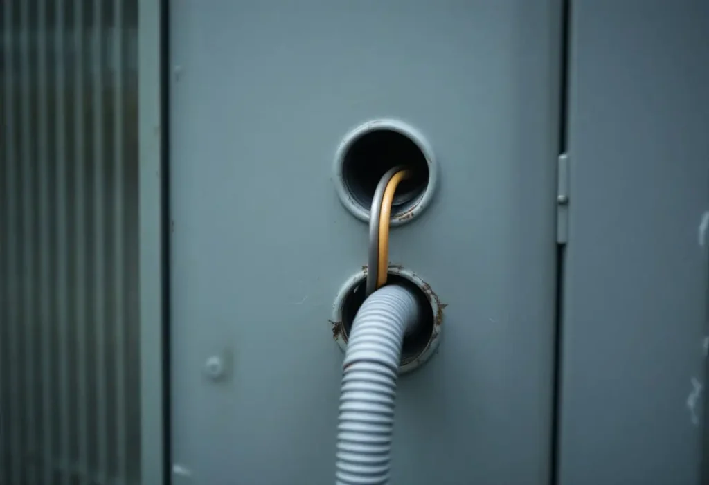
Why can’t thermostat cable ride in the AC whip, even with 600 volt insulation?
Because 725.136(A) bars the combination by circuit class, not by insulation. Section 300.3(C)(1) lets mixed circuits share a raceway when every conductor is rated for the highest voltage, and that is the trap. A later EC&M column faults CL3P cable rated 300 volts in a raceway with 277 volt circuits under 722.15(A).
The cable rating is low as well: 725.179(G) sets Class 2 cable at “not less than 150 volts,” while the Rheem units below list a 208/230 volt supply through an outdoor disconnect. Federal workplace rules agree at 29 CFR 1910.308(c)(3), which requires “a barrier or other equivalent form of protection against contact.”
Two ways share the path legally. Rewire the entire circuit in Class 1 methods under 725.130(A) Exception No. 2, then 725.48(B) lets it join power conductors of associated equipment, per Mike Holt in EC&M; Rheem writes this into its condensing unit instructions. Or strap the cable to the outside of that whip, which 300.11(B)(2) and IRC E4304.5 permit.
What do Rheem, Goodman, Resideo, Mitsubishi and Carrier write about routing?
None of these five gives a spacing for a conventional 24 volt cable. The Mitsubishi distance covers its own transmission line.
| Document | Exact wording |
|---|---|
| Rheem 92-21354-78-12, 13 and 14.5 SEER condensing units | “If the low voltage control wiring is run in conduit with the power supply, Class I insulation is required. Class II insulation is required if run separate.” |
| Goodman GSZ16 installation manual | “Route control wires through the low voltage port” |
| Resideo T6 Pro 33-00181EFS | “Use 18- to 22-gauge thermostat wire. Shielded cable is not required.” |
| Mitsubishi MXZ-SM outdoor unit manual | “(5 cm [2 inch] or more) apart from power source wiring”; “Do not insert transmission line and power source wire in the same conduit.” |
| Carrier 33ZC-15SI System Pilot (commercial) | “Do not run sensor or communication wiring in the same conduit with line-voltage wiring.” |
Compiled by The HVAC Brief from maker documents. Each row covers only the product named.
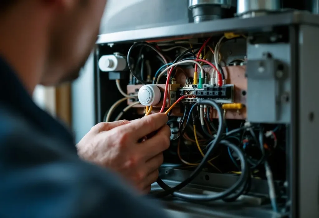
Will nearby 120 volt wiring make a thermostat or contactor misbehave?
It can fool a meter long before a contactor. Fluke explains that energized and unused wiring in close proximity “forms a capacitor,” and that meters above 1 megohm can show coupled voltage at times reaching 80 to 85 percent of the “hard” voltage.
The load tells you why. ABB’s DP contactor catalog lists a 24 volt DP20 to DP40 coil at 5 VA closed for 1 pole and 6.5 VA for 2 poles at 60 Hz, with a maximum pickup voltage of 18 V. We calculated 24 squared divided by VA: about 89 to 115 ohms, roughly 10,000 times below the meter. Our inference is that coupled voltage collapses across that coil, so it should not pull in an HVAC contactor.
Electronic inputs are the unknown: we found no maker document publishing the input impedance of a furnace board or smart thermostat. So test before rerouting. If a thermostat says cool on and nothing runs, a technician reads R to C first; Resideo rates T6 Pro terminals at 20 to 30 Vac.
For a suspect conductor, the technician lifts it at both ends and rereads on Fluke’s Auto-V/LoZ setting. A collapsing number is coupling. A number that holds is a real connection: breaker off, stop, get an electrician. Homeowners stop at the thermostat base, since the transformer primary and board compartment expose line voltage.
Which wires at a thermostat are not Class 2 at all?
Everything above assumes a listed 24 volt source. Baseboard thermostats carry 120 or 240 volts, as our thermostat wiring color guide explains, so confirm the voltage before adding a smart thermostat or any Class 2 cable.
Mini split interconnects differ too. Mitsubishi warns that on A-control wiring “there is high voltage potential on the S3 terminal.” On those units the interconnect is not thermostat wire.
Can you use 18 gauge thermostat wire for LED lights?
Only on a listed Class 2 LED driver, never on 120 volt fixtures. NEC Chapter 9 Table 11 caps Class 2 nameplates at 5.0 times the voltage in VA up to 20 volts, so 5 A at 12 volts, and 100 VA above that, so 4.17 A at 24 volts. Table 402.5 lists 6 A for 18 AWG fixture wire, but thermostat cable is not fixture wire. Voltage drop binds first.
| Load | Current | One way run | Drop | Share of source |
|---|---|---|---|---|
| 24 Vac, 40 VA transformer at full load | 1.67 A | 100 ft | 2.59 V | 10.8% |
| 12 V dc LED at the Class 2 cap | 5 A | 25 ft | 1.94 V | 16.2% |
| 24 V dc LED at the Class 2 cap | 4.17 A | 25 ft | 1.62 V | 6.7% |
HVAC Brief calculation: drop = 2 x run x 7.77 ohms per 1,000 ft x current (NEC 2008 Chapter 9 Table 8, 18 AWG solid).
Frequently asked questions
How far should thermostat wire be from electrical wire?
Beside Romex or conduit, the NEC and IRC text sets no minimum. Beside open conductors the figure is 2 in. under 725.136(I). Mitsubishi separately asks 5 cm (2 inch) for its MXZ-SM transmission line. No conventional 24 volt document we read gives a distance.
Does thermostat wire need to be in conduit?
Usually not in a house under the model code. The 2012 IRC, section E4303.2.3, lets CL2X cable under 1/4 inch diameter run without a raceway. Outdoor runs need cable identified for wet locations, per EC&M. Local amendments can add more, and the inspector decides.
Do I need shielded thermostat wire to run near power wiring?
Not for a conventional T6 Pro. Resideo’s instructions read: “Use 18- to 22-gauge thermostat wire. Shielded cable is not required.” Communicating systems differ: Carrier’s 33ZC-15SI bars its communication wiring from conduit shared with line voltage, so read that maker’s bus section.
What should I do if thermostat wire is already in a box with line voltage?
Turn the breaker off and leave the wiring alone until someone qualified sees it. The fixes under 725.136 are a separate box, a fixed barrier, or a Class 1 rewire of the entire circuit. A technician also inspects the cable jacket for damage from the box.
How we researched this
In November 2026 we read public OCR copies of NEC 2008 and the 2012 IRC, 29 CFR 1910.308, two EC&M articles and the maker documents below. The 2023 and 2026 NEC wording comes only from forum quotes and EC&M, because NFPA text is paywalled; check clause letters against your adopted edition. Excluded: contractor blogs and SEO pages, and Reddit because line voltage is involved. Coil and voltage drop figures are our arithmetic, not tests.
Sources
- NFPA. “NEC 2008,” archived copy. https://archive.org/stream/gov.law.nfpa.nec.2008/nfpa.nec.2008_djvu.txt. Accessed November 2026.
- ICC. “2012 IRC,” archived copy. https://archive.org/stream/gov.law.icc.irc.2012/icc.irc.2012_djvu.txt. Accessed November 2026.
- eCFR. “29 CFR 1910.308.” https://www.ecfr.gov/current/title-29/subtitle-B/chapter-XVII/part-1910/subpart-S/subject-group-ECFR6e1d0b3d01a4c22/section-1910.308. Accessed November 2026.
- Mike Holt, EC&M. “Remote Control and Signaling Circuits, Class 2.” https://ecmweb.com/national-electrical-code/code-basics/article/21247070/remote-control-and-signaling-circuits-class-2. Accessed November 2026.
- EC&M. “Illustrated Catastrophes.” https://www.ecmweb.com/national-electrical-code/violations/article/55394230/illustrated-catastrophes-alive-and-kickin. Accessed November 2026.
- Mike Holt Forum. “Class 2 Separation from Power.” https://forums.mikeholt.com/threads/class-2-separation-from-power.2590886/. Accessed November 2026.
- Rheem. “92-21354-78-12.” https://resource.gemaire.com/is/content/Watscocom/Gemaire/rheem_14ajm18a01_article_1374780286043_en_ii.pdf?fmt=pdf. Accessed November 2026.
- Goodman. “GSZ16 Installation Manual.” https://cdn.shopify.com/s/files/1/0253/0852/8730/files/Goodman_GSZ16_Installation_Manual__1.pdf. Accessed November 2026.
- Resideo. “T6 Pro, 33-00181EFS.” https://res.cloudinary.com/dzhpkjoqj/Resideo/33-00181EFS.pdf. Accessed November 2026.
- Mitsubishi Electric. “MXZ-SM Installation Manual.” https://s1.img-b.com/build.com/mediabase/specifications/mitsubishi/1972912/mitsubishi-mxz-sm36namhz-2-msz-fs12na-msz-fs15na-installation-sheet.pdf. Accessed November 2026.
- Carrier. “33ZC-15SI.” https://manualedistruzioni.it/carrier/remote-control/system-pilot-33pilot-01/user-manual/1so9h. Accessed November 2026.
- Fluke. “Dual Impedance Digital Multimeters.” https://www.fluke.com/en-us/learn/blog/digital-multimeters/dual-impedance-digital-multimeters. Accessed November 2026.
- ABB. “1SXU100114C0201.” https://library.e.abb.com/public/790af83132a143be97b838939fa15958/1SXU100114C0201_Definite%20Purpose%20Contactors_DGT.pdf. Accessed November 2026.
Leave a Reply