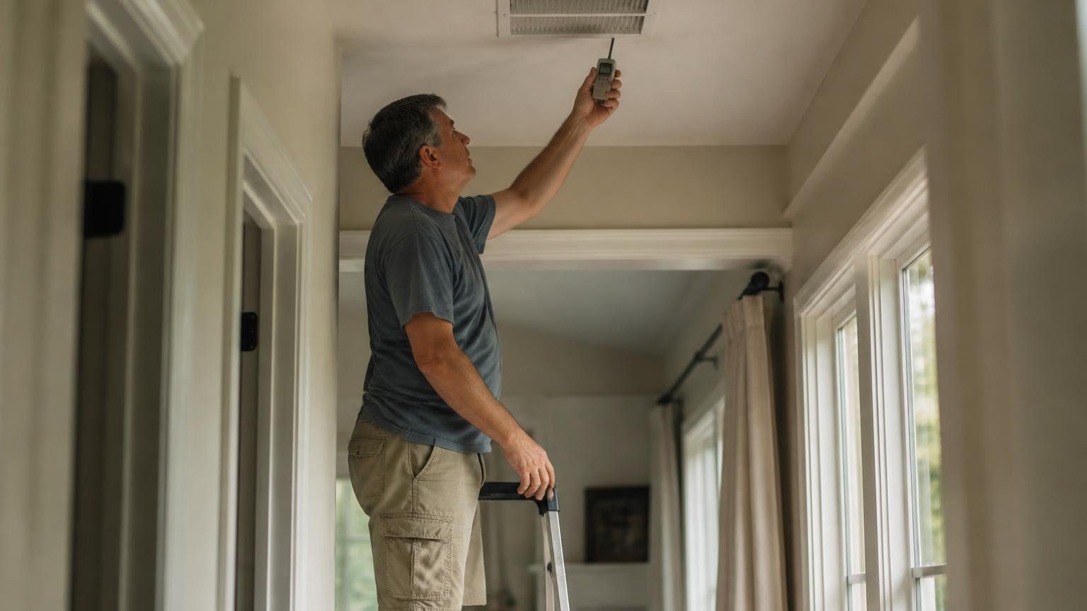
What should my AC temperature split be? Your ac temperature split, the drop from return air to supply air, should land within 3°F of a target set by indoor humidity: 18.3°F at 80°F and 67°F wet bulb, and anywhere from 15.5°F to 21.9°F in a 75°F house.
Key Takeaways
- Proctor Engineering treats a split within 3°F of its target as “probably OK” and rejects a universal 18°F to 20°F band (Proctor Engineering).
- At 80°F dry bulb and 67°F wet bulb, the federal A test indoor condition, the target split is 18.3°F (10 CFR 430, appendix M).
- ACCA calls the 15 to 20 degree split a “notoriously lousy practice” (ACCA, 2020).
- FSEC measured 130 to 510 cfm per ton across 27 Florida homes in 1996 (FSEC).
- California’s 2013 Title 24 manual dropped the temperature split method from airflow verification (Energy Code Ace).
- NIST found airflow 36% below nominal raised annual energy use 11% to 14% (NIST TN 1848, 2014).
What is an AC temperature split?
An AC temperature split, or delta T, is return air dry bulb temperature minus supply air dry bulb temperature, measured across the indoor coil during cooling. It screens two things at once: how much air crosses the coil and how much cooling the coil delivers.
Air pulled through the return grilles and pushed out the supply registers carries that heat, so a split that is off tells a technician where to look next, not what failed. The 15 to 20°F rule is a trade habit; ACCA’s Matt Akins wrote in 2020 that most technicians use a rule of thumb with “no relation to the equipment’s performance or the indoor/outdoor conditions.”
What should the temperature difference be between supply and return?
The temperature difference between supply and return should fall within 3°F of a target read from return air dry bulb and wet bulb. Proctor’s table, adapted from Carrier, CheckMe! and California Title 24, runs from 8.1°F in very humid air to 25.9°F in warm, dry air.
| Return dry bulb | 57°F wet bulb | 61°F wet bulb | 63°F wet bulb | 65°F wet bulb | 67°F wet bulb |
|---|---|---|---|---|---|
| 72°F | 20.2 | 18.2 | 17.0 | 15.5 | 13.9 |
| 75°F | 21.9 | 19.9 | 18.6 | 17.2 | 15.5 |
| 78°F | 23.5 | 21.5 | 20.2 | 18.8 | 17.2 |
| 80°F | 24.6 | 22.6 | 21.3 | 19.9 | 18.3 |
Target split, °F, from the Proctor Engineering table. Maker-derived; your equipment’s own literature takes precedence.
A Carrier “Proper Airflow Range (Cooling)” chart agrees: a 62°F proper coil leaving temperature for 80°F entering air at 67°F wet bulb, an 18°F split. Carrier says to raise fan speed if leaving air is 3°F or more too cold and lower it if 3°F or more too warm.
Why does the AC temperature split change with humidity? A worked example
The split shrinks as humidity rises because part of the coil’s work condenses water, which no dry bulb thermometer sees. Only the sensible share of capacity shows up as a temperature drop.
ACCA gives ΔT = sensible capacity ÷ 1.08 ÷ cfm, with 1.08 the constant for standard air at sea level. Its example, 17,900 Btu/h sensible at 1,000 cfm, gives 16.5°F (our division: 16.6°F).
Our worked example: a three ton system at 1,200 cfm, the convention explained in our airflow per ton explainer, with 75°F return air. Relative humidity is from the standard psychrometric equations at sea level.
- Dry, 57°F wet bulb (about 31% RH): target 21.9°F; 1.08 × 1,200 × 21.9 = about 28,400 Btu/h sensible.
- Average, 63°F wet bulb (about 52% RH): target 18.6°F, about 24,100 Btu/h sensible.
- Humid, 67°F wet bulb (about 66% RH): target 15.5°F, about 20,100 Btu/h sensible.
Same machine, same airflow, a 6.4°F spread in the healthy reading, so a low split in a humid house is not proof of a fault. If the house stays clammy at setpoint, see cool but humid houses.
How do you measure AC temperature split correctly?
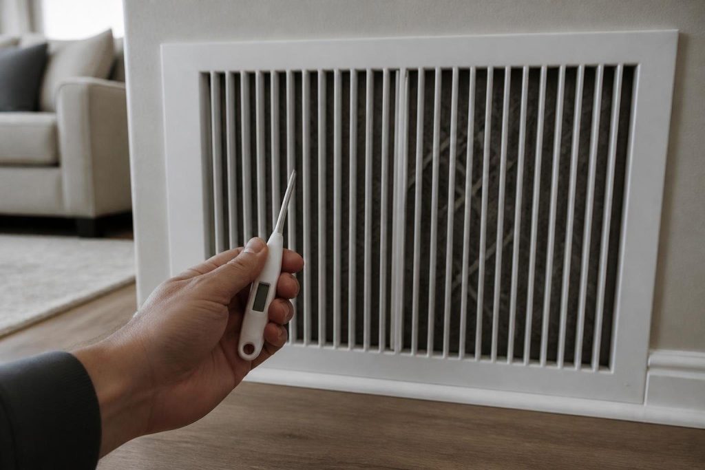
Measure in the plenums on both sides of the indoor coil after 15 minutes of steady cooling, with calibrated probes and a wet bulb reading at the return. Proctor’s order:
- Check probes in an ice bath: each should read 32°F, plus or minus 1°F.
- Run the system for 15 minutes so temperatures and pressures settle.
- Put a dry bulb probe in the supply plenum, at the center of the airflow.
- At 12 minutes, put a dry bulb probe and a wetted wet bulb probe in the return plenum.
- At 15 minutes, record return dry bulb, return wet bulb and supply dry bulb.
- Subtract supply from return, look up the target, and compare.
Proctor’s thermometer spec is plus or minus (0.1% of reading + 1.3°F), so probes can disagree by a degree before anything is wrong. The same plenum holes serve a static pressure reading.
Why a register reading misleads
A supply grille reads air that has already gained heat in the ductwork. Measure at the plenums, not at registers or hallway grilles.
What does an AC temperature split too high or too low mean?
More than 3°F above target usually means too little air across the coil; more than 3°F below usually means lost capacity from a fault other than airflow. Proctor also warns that low airflow plus low capacity can look normal.
High splits point to the air side. FSEC blamed weak airflow on “undersized return ducts and grills, improper fan speed settings, fouled filters and cooling coils,” so a clogged filter or dirty evaporator coil comes first.
Very low airflow “may lead to evaporator coil icing, refrigerant flood back and eventual compressor failure,” FSEC adds, the chain behind a frozen coil.
Low splits point to the refrigerant side once humid air is ruled out. In NIST chamber tests of a heat pump, a 30% undercharge cut capacity by almost 15% on average and COP by 12%. Test charge before assuming a system needs more refrigerant; if air moves but rooms stay warm, use our three-step not-cooling checklist.
What is the 20 degree rule in HVAC?
Neither version of the 20 degree rule is a standard. One says supply air should be about 20°F colder than return air; the other says an air conditioner can only hold a house about 20°F below outdoor temperature.
The first version fails on the evidence above. Proctor’s sheet opens by saying the split “should not universally be between 18ºF and 20ºF,” and its own targets run from 8.1°F to 25.9°F.
The second mixes two numbers: the coil sets supply temperature, while the indoor to outdoor gap depends on heat gain against capacity. The federal A test holds indoor air at 80°F dry bulb and 67°F wet bulb with 95°F outdoor air, per Table 5 of appendix M to 10 CFR part 430. We found no federal rule or ACCA document setting a 20°F limit.
Why don’t technicians trust delta T alone?
A delta T reading blends airflow and capacity into one number and cannot separate them. Proctor calls it “a useful screening tool, but not an adequate replacement for direct airflow measurement.”
Under the 2013 standards, Title 24 required measured airflow of at least 300 cfm/ton for altered systems and 350 cfm/ton for new ones before a charge test counted, noting those minimums are “far lower than the desired airflow for most systems, which is usually 400 cfm/ton and up.”
Airflow faults are common. In a 1991 PG&E study of 15 high-bill Fresno homes, Proctor found “fully two-thirds of the units studied had low airflow.” FSEC calls charge assessments made outside the 350 to 450 range “invalid.”
So the split is a first look. Once airflow checks out, charge is judged with superheat and subcooling on a manifold gauge set, and Proctor says any charge change calls for a new split test.
How we researched this
Research date: October 13, 2026. We read 12 documents and cite 8. Target splits come from Proctor Engineering’s one-page procedure, cross-checked against a Carrier chart; both are maker or utility-program data, not federal rules. Test conditions come from the eCFR, and field and fault data from FSEC, Proctor and NIST. The worked example and relative humidity values are our own arithmetic.
Excluded: contractor blogs and a training-site summary that give unsourced ranges, and Reddit and HVAC-Talk threads, read only to see what homeowners ask. No prices appear; no federal series covers this test.
Frequently asked questions
What is a normal AC delta T?
There is no single normal number. Normal is the target for your return air: Proctor’s table gives 18.6°F at 75°F dry bulb and 63°F wet bulb, and 15.5°F at 75°F and 67°F wet bulb. A reading within 3°F of the matching target is the usual pass line.
Is a 10 degree temperature split bad?
Usually, unless the return air is very humid. Proctor’s lowest targets, down to 8.1°F, apply only at high wet bulb readings. At 75°F and 63°F wet bulb the target is 18.6°F, so 10°F would be 8.6°F short, which points to lost capacity that a technician checks with superheat or subcooling.
Why is my AC temperature split too high?
A high split usually means too little air over the coil. FSEC’s 27-home study traced low airflow to undersized return ducts and grilles, wrong fan speed settings, and fouled filters and coils. Change the filter first; if the split stays more than 3°F above target, have a technician measure airflow and static pressure.
Can I measure the temperature split at the vents?
Only roughly. A register reading includes heat picked up in the ducts, and a hallway return may not match the air entering the coil. Proctor’s procedure places probes in the supply and return plenums at the center of the airflow after 15 minutes of operation, with a wet bulb reading at the return.
Does outdoor temperature change the temperature split?
Somewhat, through capacity. ACCA notes that cooling systems “will react to shifts in both indoor and outdoor temperatures,” and manufacturer expanded performance data list different sensible capacities at each condition. The Proctor target table uses only return dry bulb and wet bulb, so indoor humidity is the main input.
Is temperature split the same as temperature rise?
No. Temperature split is the drop across a cooling coil; temperature rise is the increase across a furnace or electric heat strip in heating mode. FSEC used the rise across strip heaters, with measured watts, to calculate airflow in cfm for its 27-home Florida study.
Sources
- Proctor Engineering Group. “Temperature Split Airflow Check Procedure.” https://www.proctoreng.com/dnld/Temp_airflow.pdf. Accessed October 2026.
- Akins, Matt. ACCA HVAC Blog. “A Split in Diagnosis.” June 10, 2020. https://hvac-blog.acca.org/a-split-in-diagnosis/. Accessed October 2026.
- Parker, D., et al. Florida Solar Energy Center. “Impact of Evaporator Coil Air Flow in Residential Air Conditioning Systems.” FSEC-PF-321-97. https://publications.energyresearch.ucf.edu/wp-content/uploads/2018/06/FSEC-PF-321-97.pdf. Accessed October 2026.
- Proctor, John. Home Energy. “An Ounce of Prevention: Residential Cooling Repairs.” 1991. https://www.proctoreng.com/dnld/AnOunceofPrevention-ResidentialCoolingRepairs.pdf. Accessed October 2026.
- California Energy Commission, via Energy Code Ace. “2013 Residential Compliance Manual, 4.9 Refrigerant Charge.” https://energycodeace.com/site/custom/public/reference-ace-2013/Documents/49refrigerantcharge.htm. Accessed October 2026.
- eCFR. “10 CFR part 430, subpart B, appendix M, Table 5.” https://www.ecfr.gov/current/title-10/chapter-II/subchapter-D/part-430/subpart-B/appendix-Appendix%20M%20to%20Subpart%20B%20of%20Part%20430. Accessed October 2026.
- Domanski, P., Henderson, H., Payne, W. NIST. “Sensitivity Analysis of Installation Faults on Heat Pump Performance.” Technical Note 1848, 2014. https://nvlpubs.nist.gov/nistpubs/TechnicalNotes/NIST.TN.1848.pdf. Accessed October 2026.
- Carrier. “Proper Airflow Range (Cooling)” chart, copy hosted by InspectorsJournal. https://www.inspectorsjournal.com/forum/uploads/Marc/201085205542_Temperature_Differential_Chart_Carrier.pdf. Accessed October 2026.
Leave a Reply