What is a normal static pressure HVAC reading? About 0.50 in. w.c. of total external static pressure for most home furnaces, air handlers and heat pumps, the point federal test procedures rate them at. Readings above 0.8 in. w.c., the ceiling one federal utility program accepts, mean the ducts, filter or coil are choking airflow.
Key Takeaways
- SEER2 testing rates conventional ducted systems at 0.50 in. wc. minimum (10 CFR 430 appendix M1, Table 4), up from 0.10 to 0.20 under the old SEER test.
- Furnace fans are tested at 0.50-0.55 in. wc. with a factory coil and 0.65-0.70 without one, per Table 1 of appendix AA.
- DOE’s review of 20 field studies covering 1,010 home systems found 0.20 to 0.70 in. wc. (80 FR 69318, 2015).
- LBNL found PSC blower airflow loss at installed pressures cut air conditioner efficiency 10% (LBNL-62344, 2008).
- The Bonneville Power Administration’s PTCS program accepts up to 0.8 in. w.c.; most manufacturers suggest 0.5 or less.
What is static pressure in an HVAC system?
Static pressure is the resistance the blower pushes against: filter, coil, ducts, registers and grilles. Total external static pressure (TESP) measures it outside the cabinet, return side plus supply side, in inches of water column (in. w.c. or IWC).
Section 2.4 of appendix AA, the federal furnace fan test, defines it as “the difference between static pressures measured in the outlet duct and return air opening.” Our ductwork and airflow overview covers the basics; this page covers the numbers, the test and the fixes.
One trap: on a refrigerant system, “static pressure” means standing pressure with the unit off, read on gauges against a refrigerant pressure-temperature chart.
What should static pressure be? The federal rating points
For a conventional ducted furnace, air handler or heat pump, 0.50 in. w.c.: the pressure DOE test procedures rate equipment at, and the closest thing to a published “normal.” Your unit’s blower table sets the real limit.
| Federal test and product | Rating static pressure (in. w.c.) | Where it is written |
|---|---|---|
| SEER2 test, conventional ducted AC or heat pump | 0.50 minimum | Appendix M1, Table 4 |
| SEER2 test, mobile home, ceiling or wall mount, mid-static, space-constrained | 0.30 minimum | Appendix M1, Table 4 |
| SEER2 test, low-static multi-split | 0.10 minimum | Appendix M1, Table 4 |
| SEER2 test, small duct, high velocity | 1.15 minimum | Appendix M1, Table 4 |
| Old SEER test, non-SDHV systems | 0.10 to 0.20 by capacity | Appendix M, Table 4 |
| Furnace fan, factory evaporator coil inside | 0.50-0.55 | Appendix AA, Table 1 |
| Furnace fan, built for a coil but tested without one | 0.65-0.70 | Appendix AA, Table 1 |
| Furnace fan, mobile home | 0.30-0.35 | Appendix AA, Table 1 |
M and M1 values: January 1, 2023 eCFR edition. Since July 7, 2025, appendix M1 cites AHRI 210/240-2024 instead of printing the table.
Filters change the comparison. Appendix M1 adds 0.08 in. w.c. when a unit is tested without a filter, and appendix AA removes filters entirely, yet your filter sits inside every field reading. The SEER2 efficiency floors assume air moving at the rated pressure.
Correction: 0.5 is a rating point, not a code limit
Many pages call 0.5 “the maximum.” No federal rule caps installed static pressure. DOE rates equipment at 0.50, and ENERGY STAR compares measured TESP with the design value. A system above 0.5 is acceptable if its blower table still delivers design airflow.
Where does the 0.5 inch static pressure number come from?
It comes from DOE field data plus an allowance for dirt. In its November 2015 test procedure proposal, DOE reviewed 20 field studies published from 1995 to 2007, covering 1,010 home system assessments. It “observed measured ESPs to range from 0.20 to 0.70 in. wc.”
Blending three statistical methods, DOE settled on 0.32 in. wc. as typical for a new system. It then added 0.13 for a loaded filter and 0.07 for a fouled evaporator coil, because lab units are clean and field units are not. The January 2017 final rule adopted 0.50 in. wc. for conventional systems of all capacities, as an industry working group recommended.
LBNL’s Iain Walker recommended rating at “realistic system static pressures of between 0.5 and 0.8 in. water,” and rebates only for systems with a field-measured static pressure below 0.5. Treat 0.5 as the target and 0.8 as a warning line.
How do you measure total external static pressure with a manometer?
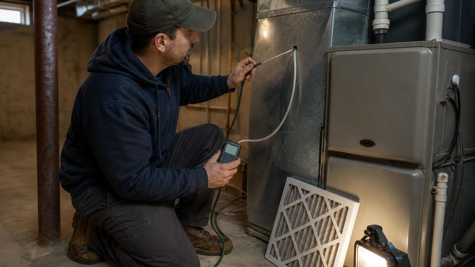
Drill a test hole in the return between filter and equipment and one in the supply plenum, read each with a static pressure probe on a manometer, and add the two numbers ignoring signs. The ENERGY STAR National HVAC Commissioning Checklist (Rev. 14, items 3.2 to 3.5) records TESP this way.
- Run the mode with the higher design airflow, usually cooling, with all registers open.
- Zero a dual-port digital manometer, a tool most HVAC tool kits now carry.
- Drill the return hole after the filter, before the cabinet. The Bonneville Power Administration’s PTCS guide says most maker fan tables assume this spot.
- Drill the supply hole in the plenum, clear of the coil and elbows. On a gas furnace, read the coil drop separately, as the National Comfort Institute diagram ENERGY STAR hosts advises.
- Face the static pressure tip into the airflow; BPA says readings without a probe are not valid.
- Add the two values and read airflow off the maker’s fan table at that pressure and blower speed.
- Plug the holes.
In BPA’s worked example, 0.28 return plus 0.34 supply gives 0.62 in. w.c. At 0.60 the table shows 1078 CFM on medium speed, 359 CFM per ton on a 3-ton heat pump, inside PTCS’s 325 to 500 band for airflow per ton. Fan tables often assume a dry coil, so a wet coil delivers less.
What are the symptoms of high static pressure in HVAC?
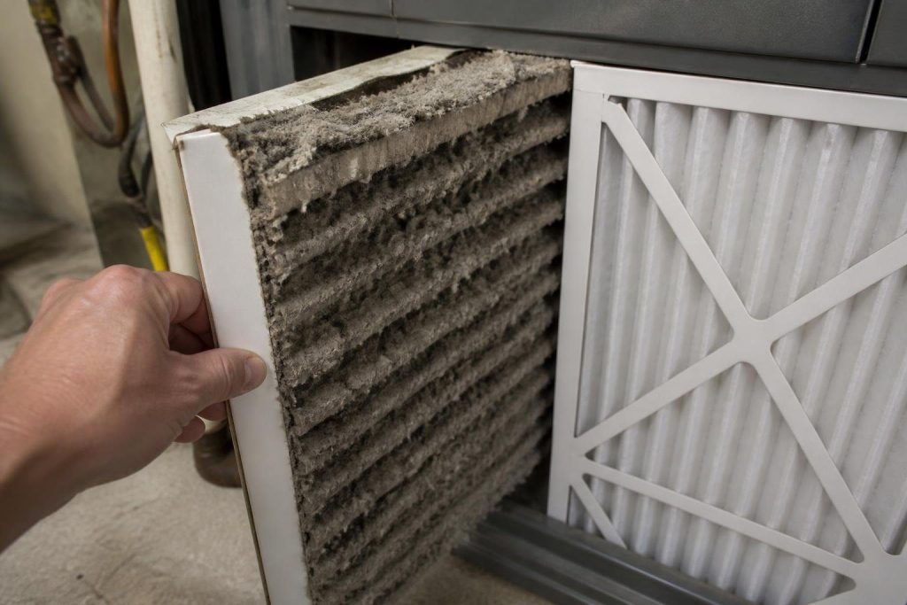
High static pressure shows up as weak or whistling registers, rooms that never reach setpoint, a coil that ices in cooling, and a furnace that trips its high limit switch in heating. All four trace to the same cause: less air crossing the coil or heat exchanger than the equipment was built for.
How much air you lose depends on the blower motor. Maker data in Goodman’s GM9S80 specification sheet, a multi-speed ECM furnace, shows the 80,000 Btu/h model’s default cooling tap moving 1,426 cfm at 0.1 in. w.c., 1,229 at 0.5 and 1,078 at 0.8. That is about 12% less air than at the rating point, by our arithmetic.
| Blower motor type | What rising static pressure does | Evidence |
|---|---|---|
| PSC (older furnaces and air handlers) | Airflow falls; power stays similar | LBNL-62344: lost airflow cut AC efficiency 10% |
| Multi-speed ECM (constant torque) | Airflow falls along the fan table | Goodman GM9S80: 1,229 cfm at 0.5, 1,078 at 0.8 |
| Variable-speed ECM (constant airflow) | Holds airflow by drawing more power, until it runs out of range | LBNL: BPM motors hold airflow, but their energy edge shrinks |
The last row hides the symptom: a constant-airflow motor masks choked ducts until it fails, as our guide to PSC and ECM blower motors explains. LBNL flagged the “safety implications of the PSC’s lower airflow” in heating, which is the limit-switch problem.
How do you fix high static pressure, cheapest first?
Start cheap and re-measure after each fix. Separate return and supply readings show which half of the system is choking.
| Fix, in order | Typical cost tier | Why it lowers static pressure |
|---|---|---|
| 1. Replace the filter or move to a deeper, larger one | Owner job | DOE puts the average fouled-filter penalty at 0.13 in. wc. |
| 2. Open closed registers and dampers | Owner job | Each closed outlet adds resistance |
| 3. Pull flex duct tight and support it | Small service call | Sag and compression raise pressure drop |
| 4. Clean the evaporator coil | Technician | DOE puts average coil fouling at 0.07 in. wc. |
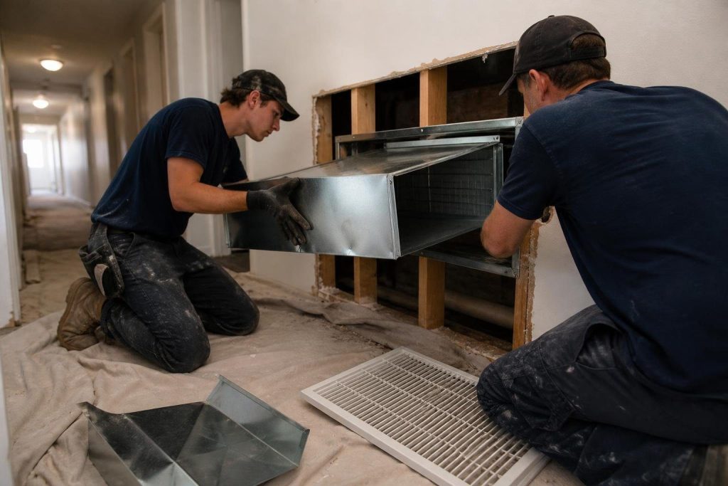
| 5. Add return area or enlarge the return drop | Duct work | Undersized returns are a common cause |
A high-MERV filter in a thin slot is the usual first suspect; why filter area matters more than MERV explains the trade. Closing vents to push air elsewhere backfires, as our explainer on how duct dampers work shows.
Our page on flex duct sag and compression shows how fast a sloppy run eats the budget. If the return reads higher than the supply, more return area is usually the fix.
Is low static pressure a problem?
Rarely. A conventional system reading well under 0.3 in. w.c. usually means a test mistake, a missing access panel or big duct leaks; only low-static multi-split units are rated as low as 0.10. If rooms stay uneven at a normal reading, the problem is distribution, which room-by-room air balancing addresses.
How we researched this
Research date: October 13, 2026. We read the federal test procedures directly from eCFR (appendices M, M1 and AA), DOE’s 2015 proposal and 2017 final rule, LBNL report 62344, the ENERGY STAR checklist and BPA’s PTCS guide. Maker data comes from one Goodman sheet, labelled as such. We consulted 16 documents, including the top three ranking pages, and cite 10. Excluded: contractor blogs, unsourced “normal range” claims, and a 1997 New Jersey survey that measured plenum pressures, not TESP. No Reddit; Google’s People Also Ask questions shaped the FAQ.
Frequently asked questions
Is .05 static pressure good?
If you mean 0.5 in. w.c., yes: it is the minimum conventional ducted systems are rated at under appendix M1, Table 4. A true reading of 0.05 on a ducted furnace is suspiciously low and usually means a probe facing the wrong way or a port in turbulence.
What happens if static pressure is too high?
Airflow drops or the blower works harder. Goodman’s GM9S80 table shows its default cooling tap falling from 1,229 cfm at 0.5 in. w.c. to 1,078 cfm at 0.8. LBNL found the lost airflow of a PSC blower cut air conditioner efficiency 10% at installed pressures.
How do you calculate total external static pressure?
Add the return reading and the supply reading, ignoring the minus and plus signs. ENERGY STAR’s commissioning checklist does exactly this in items 3.3 to 3.5. In BPA’s example, a return of 0.28 and a supply of 0.34 give 0.62 in. w.c.
What should static pressure be on a furnace?
Check its blower table first. Furnace fan testing under appendix AA uses 0.50-0.55 in. wc. for units with a factory coil and 0.65-0.70 for units built to take an add-on coil, measured without the coil installed. Mobile home furnaces are tested at 0.30-0.35.
Does a higher MERV filter raise static pressure?
It can, especially in a thin one-inch slot. DOE estimated a loaded filter adds an average 0.13 in. wc. over a clean one, and SEER2 testing adds 0.08 when a unit is rated without a filter. More filter area offsets a higher rating.
What tool measures HVAC static pressure?
A manometer reading in inches of water column, fitted with static pressure tips. Dual-port digital models read both sides at once. BPA’s PTCS guide says readings without a static pressure probe are not valid, and the tip faces into the airflow.
Sources
- eCFR. “10 CFR 430 Appendix M1 (January 1, 2023 edition).” https://www.ecfr.gov/on/2023-01-01/title-10/chapter-II/subchapter-D/part-430/subpart-B/appendix-Appendix%20M1%20to%20Subpart%20B%20of%20Part%20430. Accessed October 2026.
- eCFR. “10 CFR 430 Appendix M (January 1, 2023 edition).” https://www.ecfr.gov/on/2023-01-01/title-10/chapter-II/subchapter-D/part-430/subpart-B/appendix-Appendix%20M%20to%20Subpart%20B%20of%20Part%20430. Accessed October 2026.
- eCFR. “10 CFR 430 Appendix M1 (current).” https://www.ecfr.gov/current/title-10/chapter-II/subchapter-D/part-430/subpart-B/appendix-Appendix%20M1%20to%20Subpart%20B%20of%20Part%20430. Accessed October 2026.
- eCFR. “10 CFR 430 Appendix AA, Furnace Fans.” https://www.ecfr.gov/current/title-10/chapter-II/subchapter-D/part-430/subpart-B/appendix-Appendix%20AA%20to%20Subpart%20B%20of%20Part%20430. Accessed October 2026.
- U.S. DOE. “Central Air Conditioner and Heat Pump Test Procedure SNOPR, 80 FR 69278 (2015).” https://www.govinfo.gov/link/fr/80/69318?link-type=pdf. Accessed October 2026.
- U.S. DOE. “Central Air Conditioner and Heat Pump Test Procedure Final Rule, 82 FR 1426 (2017).” https://www.govinfo.gov/content/pkg/FR-2017-01-05/pdf/2016-30004.pdf. Accessed October 2026.
- Lawrence Berkeley National Laboratory. “Comparing Residential Furnace Blowers for Rating and Installed Performance (LBNL-62344).” https://eta-publications.lbl.gov/publications/comparing-residential-furnace-blowers. Accessed October 2026.
- U.S. EPA, ENERGY STAR. “National HVAC Commissioning Checklist (Rev. 14).” https://www.energystar.gov/sites/default/files/2025-01/National%20HVAC%20Commissioning%20Checklist_Rev%2014.pdf. Accessed October 2026.
- Bonneville Power Administration. “PTCS External Static Pressure: CFM Manufacturer Lookup Tables.” https://www.bpa.gov/-/media/Aep/energy-efficiency/residential/residential-ptcs-essentials/ptcs-esp-cfm-lookup-tables-final.pdf. Accessed October 2026.
- National Comfort Institute, hosted by ENERGY STAR. “Measure and Interpret Static Pressures.” https://www.energystar.gov/sites/default/files/specs/National%20Comfort%20Institute%20-%20Measure%20and%20Interpret%20Static%20Pressures.pdf. Accessed October 2026.
- Goodman (maker data). “GM9S80/GC9S80 Specification Sheet, SS-GM9S80/GC9S80 (8/21).” https://cdn.shopify.com/s/files/1/0794/3104/1346/files/GM9S80_GC9S80_Spec_Sheet.pdf. Accessed October 2026.
Leave a Reply