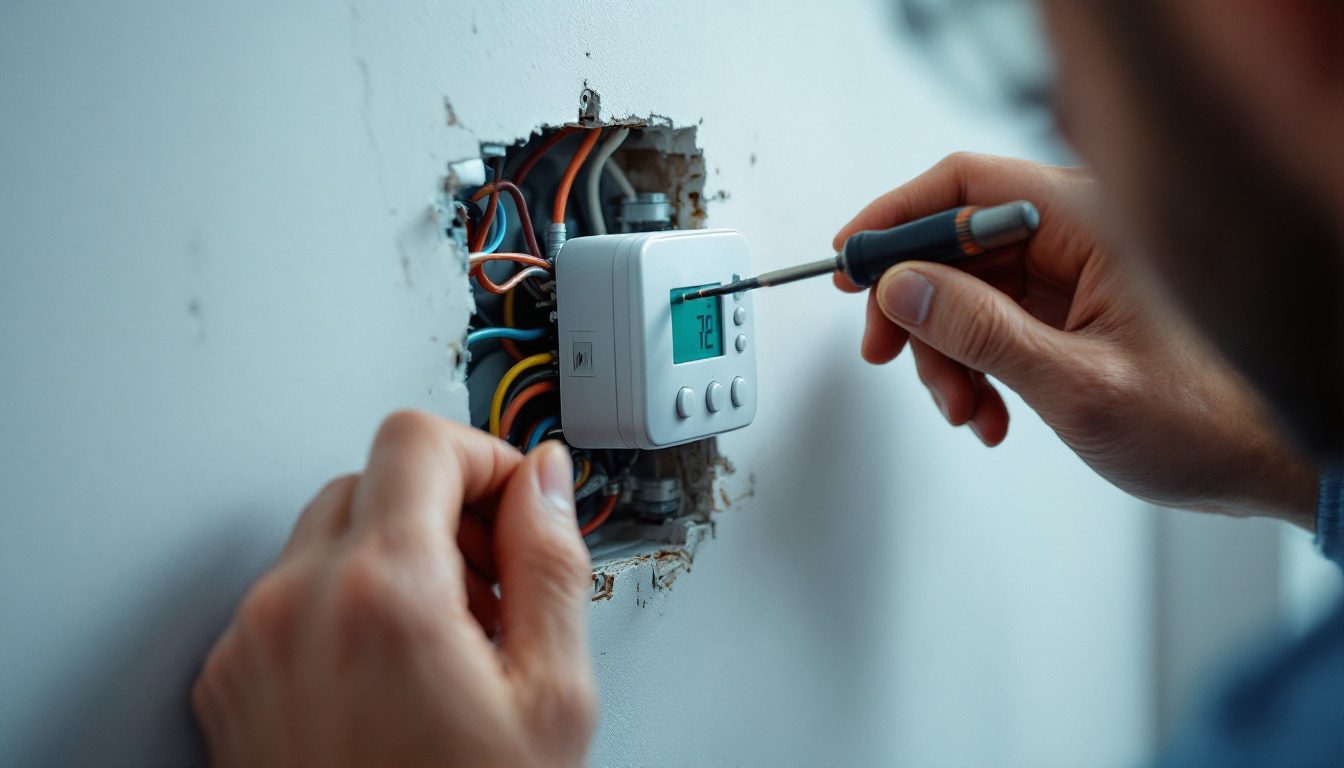
What is the thermostat wiring color code? It is a convention, not a standard: red to R (power), white to W (heat), yellow to Y (cooling), green to G (fan), blue or black to C (common). Honeywell Home says no code governs wire colors, so you wire by the terminal letter, never the color.
Key Takeaways
- “There is no code governing wire colors and thermostat connections,” says Honeywell Home (Resideo).
- Sensi (Copeland) lists the most common colors: red R, white W, yellow Y, green G, and blue or black C.
- Google Nest says O/B wires are typically orange and common wires typically blue, but a blue wire on a B terminal most likely belongs on C.
- Resideo’s T6 Pro terminals are rated 20 to 30 Vac and take 18 to 22 gauge wire (T6 Pro instructions).
- Line voltage (120 or 240 volt) baseboard systems are incompatible with a low voltage thermostat (Copeland 1C26 sheet).
- On a heat pump, backup heat wires to AUX or E, not W (RTH6360 guide).
What is the thermostat wiring color code?
The thermostat wiring color code is a habit installers share, not an enforced rule. Honeywell Home says to wire by the letters next to the terminal block, and Sensi says wire coloring “is not standard across all types of thermostats.”
The habit is still useful as a first guess: Sensi lists red for R, white for W, yellow for Y, green for G, and blue or black for C as the most common colors. Confirm each one at the equipment. Our explainer on how a thermostat decides when to call for heat covers the control logic these wires carry.
Correction
Several ranking pages call thermostat colors “standardized.” Honeywell Home, Sensi and Google Nest, who write the installation guides, each say not to rely on color.

Thermostat wiring color chart: what does each terminal letter mean?
Each letter names a circuit. Functions below come from Resideo and Copeland terminal lists and Google Nest; colors come from Sensi and Google Nest. Where no manufacturer names a usual color, we say so.
| Terminal | What it does | Usual color |
|---|---|---|
| R | 24 VAC power from the transformer | Red |
| Rh | 24 VAC power, heating | Red |
| Rc | 24 VAC power, cooling | Red |
| C | 24 VAC common | Blue or black |
| W or W1 | Heat, stage 1 | White |
| W2 | Heat, stage 2 | No usual color |
| Y or Y1 | Compressor, stage 1 | Yellow |
| Y2 | Compressor, stage 2 | No usual color |
| G | Fan relay (blower) | Green |
| O | Valve energized in cooling | Orange |
| B | Valve energized in heating, or a common | Blue on B: likely common |
| O/B | Changeover, set to O or B | Orange; brown on some |
| E | Emergency heat | No usual color |
| AUX | Heat pump backup heat | No usual color |
| S | Wired sensor input | No usual color |
| L or L/A | Heat pump fault input | No usual color |
C, per Copeland’s universal thermostat instructions, is the “common wire from secondary side” of the transformer. B means two things: a heating changeover valve on some heat pumps, a common on others.
How are 2, 4 and 5 wire thermostats wired?
Count the conductors, then match the pattern. Copeland’s 1C26 sheet describes standard heating and cooling systems as “4 or 5 wires,” and Resideo’s T6 Pro wiring tables show the letters each system uses. A 2 wire cable, R and W, runs heat only equipment.
| Pattern | Typical system | Terminals used |
|---|---|---|
| 2 wire | Heat only: furnace, boiler or zone valve | R, W |
| 4 wire | Furnace or air handler with central air, no C | R, W, Y, G |
| 5 wire | Same system with continuous power | R, W, Y, G, C |
| Heat pump | Heat pump with backup heat | R, C, Y, G, O/B, AUX or E |
| 2 stage | Two stage heat and cool | Adds W2 and Y2 |
A 4 wire system has no C, the usual blocker for a Wi-Fi model; our smart thermostat installation guide covers the fixes. If cooling stopped after a swap, rule out a wire on the wrong letter, then use our AC not turning on checklist before calling.
Which thermostat wiring colors change on a heat pump?
On a heat pump, the thermostat wiring colors mostly stay put, but three letters change jobs. Y runs the compressor in both modes, per Google Nest, since one compressor heats and cools. O/B drives the reversing valve. Backup heat moves off W: Resideo says “Do NOT use W for heat pump applications.”
Copeland defines O as the changeover valve “energized constantly in cooling” and B as energized in heating, and ships its universal thermostat set to O for “the majority of heat pump applications.” Our reversing valve explainer covers which brands use B and what a wrong setting does.
- Find the old wire on O, B or O/B and put it on O/B.
- If the old thermostat had separate O and B wires, Resideo says the B wire goes to C.
- Set the system type to heat pump and choose O or B in setup.
AUX and E are separate calls; see auxiliary versus emergency heat. A heat pump paired with a gas furnace needs a thermostat built for that; see our dual fuel heat pump guide.

Where does the 24 volt power come from?
R and C are the two ends of a 24 volt transformer’s secondary, usually in the furnace or air handler. Sensi describes R as “24 VAC power from the transformer in your gas furnace.” To call for heat, cooling or fan, the thermostat connects R to W, Y or G.
Systems with separate heating and cooling transformers use Rh and Rc. Resideo’s T6 Pro joins R and Rc with a slider tab on one transformer systems and takes C from the cooling transformer on two transformer systems. Resideo’s AT140A, a 40 VA transformer for 24 Vac circuits, meets NEC Class 2 and UL 1585.
Class 2 is why thermostat cable stays apart from house wiring. Under OSHA’s 29 CFR 1910.308(c), a Class 2 source must be listed and marked, and Class 2 conductors may not share a box or raceway with power conductors unless a barrier separates them. Copeland’s universal model allows 1.5 A per terminal. Y only energizes a relay outdoors, the HVAC contactor.
Which systems must never get a 24 volt thermostat?
Line voltage and millivolt systems must never get an ordinary 24 volt thermostat. Copeland’s 1C26 sheet lists “Baseboard Electric Heating or Line Voltage (120 or 240 Volt)” as not compatible, and millivolt systems supply far less power than a low voltage thermostat expects.
Look before you unscrew anything. Google Nest says line voltage thermostats are usually labeled 110, 115, 120 or 240 VAC with 2 to 4 thick wires. Resideo adds thick black wires with wire nuts; with either sign, “the thermostat will not work.” These usually serve electric baseboard heaters, and they need a line voltage model.
Millivolt systems, per Google Nest, are typically wall or floor heaters, and they “can’t deliver the right amount of power” to a Nest. Sensi lists both types as incompatible with every Sensi model. Some battery thermostats do support millivolt: Copeland lists “Millivolt Heat Only Systems” for floor or wall furnaces. Our wall heater guide explains those units.
What if the wire colors do not match the terminal letters?
Go by the letters; when they are missing, go to the equipment. Honeywell Home says to trace each wire back to the furnace, air handler, heat pump or AC unit and read the terminal it lands on.
- Photograph the terminals with letters visible, then label each wire by letter.
- Translate old letters. Resideo maps F to G, M to Y, H to W, and C1, X or B to C on conventional systems.
- Remove old jumpers; use the new thermostat’s jumper if there is one R wire.
- If a letter cannot be confirmed at the board, call a licensed technician.
Blue is the classic trap: Google Nest says a blue wire on B most likely belongs on C, while a heat pump’s B setting means something else.
How we researched this
Researched October 8, 2026. We read installation instructions and support pages from Resideo (Honeywell Home), Google Nest, Sensi and Copeland White-Rodgers, a Resideo transformer listing, and OSHA’s 29 CFR 1910.308 on eCFR. Manufacturer documents are Tier 2 and describe their own products. We consulted 18 primary documents and cite 10. Contractor blogs, AI content sites and PDF spam ranking for this keyword were excluded: none sources its color claims. Reddit was not used because the topic involves line voltage. No prices are published.
Frequently asked questions
What color is the C wire on a thermostat?
Usually blue or black, but not always. Sensi says the C wire’s color is not standard, though most systems use blue or black, and Google Nest says common wires are typically blue. C is the 24 VAC common from the transformer’s secondary side, so confirm it at the terminal marked C on the furnace or air handler.
What voltage is on thermostat wires?
About 24 volts AC on a standard system. Resideo’s T6 Pro rates its terminals at 20 to 30 Vac, and Google Nest asks for 20 to 30 V when a step down transformer is added. Line voltage thermostats on baseboard heat carry 120 or 240 volts, and millivolt heaters far less, so neither takes a standard thermostat.
How do you wire a thermostat with only 2 wires?
A 2 wire cable is normally R and W, heat only: the thermostat connects R to W to call for heat. Copeland’s 1C26 sheet lists 2 wire hot water zone heat among compatible systems. Two wires cannot add cooling or a fan and supply no C, so most Wi-Fi models need more conductors or an adapter.
Does the orange wire go to O or B?
Usually to the O/B terminal, set to O. Google Nest says O/B wires are typically orange. Copeland ships its universal thermostat set to O, energized in cooling, because that fits the majority of heat pumps; equipment that energizes the valve in heating needs B. If heating and cooling come out reversed after a swap, check that setting first.
Do I need a jumper between Rh and Rc?
Only when one transformer powers both heating and cooling. Resideo’s T6 Pro joins R and Rc with a slider tab on those systems, and separates them on two transformer systems, taking C from the cooling transformer. One red wire means use the jumper; two separate R wires mean leave it open.
Can I put a regular thermostat on electric baseboard heat?
No. Baseboard heat usually runs a line voltage thermostat labeled 110, 115, 120 or 240 VAC, per Google Nest, and Copeland lists 120 or 240 volt line voltage as not compatible with its low voltage 1C26. Resideo says a standard thermostat “will not work” there. Use a line voltage model rated for the heater, and switch off the breaker first.
Sources
- Honeywell Home (Resideo). “Do the color of the wires correspond to the letters on my new thermostat?.” https://www.honeywellhome.com/blogs/support/wi-fi-7-day-touchscreen-thermostat-install-4. Accessed October 2026.
- Google. “Identify a thermostat wire. Google Home and Nest Help.” https://support.google.com/googlehome/answer/9452748?hl=en. Accessed October 2026.
- Google. “Nest thermostat compatibility. Google Nest Help.” https://support.google.com/googlenest/answer/9240316?hl=en. Accessed October 2026.
- Sensi (Copeland). “What is a C-Wire or Common Wire and How do I Know if I Have One?.” https://sensi.copeland.com/en-us/support/what-is-a-common-wire. Accessed October 2026.
- Copeland White-Rodgers. “Universal Thermostat Installation and Operating Instructions (0037-7052).” https://media.copeland.com/d8ab64ea-5605-4e47-ab22-b16d001d7970/0037-7052-Instructions-Universal%20Thermostat.pdf. Accessed October 2026.
- Copeland White-Rodgers. “Installation Instructions, Heating only 1C20 and Heating and Cooling 1C26 (0037-6335B).” https://media.copeland.com/fed84150-98ab-4bd5-8f5c-b16b00f85225/0037-6335B-Instruction%20Sheet-Heating%20only%201C20%20and%20Heating%20and%20Cooling%201C26.pdf. Accessed October 2026.
- Resideo. “RTH6360 Series Programmable Thermostat Quick Installation Guide (33-00201EF).” https://customer.resideo.com/resources/techlit/TechLitDocuments/33-00000s/33-00201EF.pdf. Accessed October 2026.
- Resideo. “T6 Pro Programmable Thermostat Installation Instructions (33-00181EFS).” https://customer.resideo.com/resources/techlit/TechLitDocuments/33-00000s/33-00181EFS.pdf. Accessed October 2026.
- Resideo. “AT140A1000 40 VA Multisystem Mount Transformer.” https://resideo.com/us/en/pro/products/gcs/transformers/at140a1000-40-va-multisystem-mount-transformer-at140a1000-u. Accessed October 2026.
- Occupational Safety and Health Administration. “29 CFR 1910.308, Special systems. eCFR.” https://www.ecfr.gov/current/title-29/subtitle-B/chapter-XVII/part-1910/subpart-S/subject-group-ECFR6e1d0b3d01a4c22/section-1910.308. Accessed October 2026.
Leave a Reply