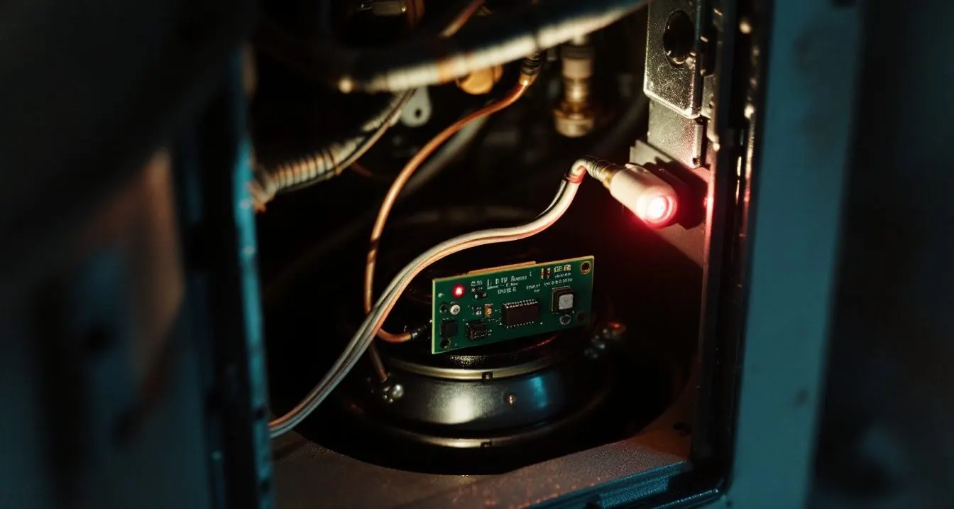
Trane furnace error codes depend on the control board. On Trane’s LED boards 2 red flashes means lockout, 3 a pressure switch fault and 4 an open limit, except on the three-LED board, where 2 flashes means the pressure switch is stuck closed. S8 and S9 display boards show codes such as E2.1, ignition retries exceeded.
Which Trane board do you have: one LED, two, three or a display?
Look at the integrated furnace control (IFC) behind the blower door before touching anything. Trane shows four layouts: one red LED, a green and red pair, a green, amber and red trio, or a 7-segment display with Menu and Option buttons. They list model numbers, not XR or XV names, so match the rating plate.
American Standard owners can use the same tables: Trane kit guides mark the first model letter “May be A or T”, and guide 18-CH111D1 lists AUX and ADX models beside TUX and TDX for one control. See our HVAC brand ownership table.
What do Trane’s E-codes like E2.1, E3.1 and E04 mean on S8 and S9 furnaces?
On the S8B1, S8X1, S8X2, S9B1, S9X1 and S9X2 the display lists alarms under the Err menu. Trane draws the decimal low on the digit, so “E2 1” is E2.1. E3.3 and E3.4 apply only to the two-stage S8X2 and S9X2, per Trane 18-CE12D1 and 18-CE16D1.
| Code | Trane’s wording | Owner check | Technician tests |
|---|---|---|---|
| E01 | Loss of the IRQ or other internal failures (internal IFC error) | One power cycle | Board |
| E2.1 | Retry exceeded (flame never sensed, one hour lockout after 3 times) | Gas valve handle open | Igniter, gas pressure |
| E2.2 | Recycles exceeded (flame sensed then lost, one hour lockout after 10 times) | Vent terminations clear | Flame current, ground |
| E2.3 | 1st stage gas valve not energized when it should be, exceeded after 10 times | No | Valve circuit |
| E3.1 | Shorted pressure switch, 1st stage | No | Switch, wiring |
| E3.2 | Open pressure switch, 1st stage | Vents clear of snow; tubing on | Draft at switch, trap |
| E3.3 | Shorted pressure switch, 2nd stage (S8X2, S9X2 only) | No | PS2 |
| E3.4 | Open pressure switch, 2nd stage (S8X2, S9X2 only) | As E3.2 | PS2 draft |
| E04 | Open limit (main thermal, rollout switch, or reverse airflow switch) | Filter, registers | Which switch, temperature rise |
| E05 | Flame detected, should not be present | Stop: shut gas | Gas valve |
| E6.1 | Voltage reversed polarity | Stop: line voltage | Hot leg on BLACK lead |
| E6.2 | Bad grounding | Stop: line voltage | Ground path |
| E6.3 | Igniter relay fails, or igniter open | No | Igniter, relay |
| E7.1 | 1st gas valve (MVL) is energized when it should be off | Stop: shut gas | Board, valve |
| E08 | Flame current is low, but still strong enough to allow operation | No | Flame current |
| E09 | Open inducer limit switch or condensate pressure switch | Drain not blocked | Trap, inducer limit |
| E11 | Five gas valve relay or stage faults | Stop | Valve relays |
| E12 | Open fuse | No | 24 volt short, 5 amp fuse |
Is Trane code 1 dL or 7P1 an error?
No. “1 dL” is IdL, which Trane defines as Idle: power on, no thermostat call; the 7-segment capital I looks like a 1. Other status words: Ht, Ht1 and Ht2 for gas heat, CL1 and CL2 for cooling on the S9X2 (CP1 and CP2 on the S9X1), HP1 and HP2 for heat pump. American Standard Gold and Silver furnaces carry these same boards, and the American Standard furnace error codes treat COF, ARF and IdL as status readouts rather than faults.
During a call the S9X display alternates status with the blower speed tap, written “tp7 = Speed Tap 7”. No Trane document we opened defines 7P1; our reading is tP1, speed tap 1. The S9V2 and L8V1 guides (18-CE03D1, 18-CE15D1) add Lr1 for the inducer learning routine, A-F followed by “airflow times 10”, and dFt for defrost, but print no alarm table.
What does a Trane furnace blinking 2, 3 or 4 times mean on each LED board?
Count red flashes between pauses. The single LED control (18-CH52D1) and green and red boards (18-CH92D1, 18-CH111D1) share one numbering; *UD2 and *DD2 ACV models (18-CH76D1) change flashes 6, 9 and 10. The three-LED board (18-CH61D1, X341956P04) renumbers nearly everything.
| Red flashes | Single red LED and green + red boards | Three-LED board (green, amber, red) | Closest display code |
|---|---|---|---|
| 1 | Normal, one flash every 20 seconds (green + red) | Flame sensed when no flame should be present | E05 |
| 2 | System lockout, retries or recycles exceeded | Pressure switch stuck closed | E2.1, E2.2 / E3.1 |
| 3 | Pressure switch fault (single LED: draft pressure error) | 1st stage pressure switch stuck open | E3.2 |
| 4 | Open limit (single LED: open temperature limit circuit) | Open limit (X341956P04: thermal limit or rollout) | E04 |
| 5 | Flame sensed when no flame should be present | Open rollout, open fuse detect | E05 / E04, E12 |
| 6 | 115 volt AC power reversed or improper ground | Pressure switch cycle lockout | E6.1, E6.2 |
| 7 | Gas valve circuit error | External lockout (retries) | E7.1 / E2.1 |
| 8 | Low flame sense signal | External lockout (recycles) | E08 / E2.2 |
| 9 | Igniter relay fault (ACV models: open inducer limit) | Grounding or reversed polarity | E6.3 / E6.1 |
| 10 | Communication fault (ACV models only) | Gas flow with no call for heat | none / E7.1 |
| 12 | Not listed | Igniter failure (X341956P04: replace IFC) | E6.3 |
The trap is 2 flashes: ignition lockout on a green and red board, a pressure switch stuck closed on a three-LED board. The single LED table adds “system voltage too low” to 6 flashes; for 9, line N to 24 VAC common should read 2 volts or less.
Why is a Trane furnace blinking green and red, amber, or a steady light?
On the green and red boards in 18-CH111D1, a slow green flash is normal with no call, a fast green flash is a call for heat, both LEDs on is internal control failure and both off is an open fuse. A single red LED that stays on means replace IFC; off means check power. The thermostat on the wall has flashing words of its own, and the Trane thermostat flashing guide separates compressor delays from Call for Service warnings.
Three-LED board amber: 1 flash first stage heat, 2 second stage, 3 W2 with no W1, 4 Y with no G call, rapid for low flame sense current. One green flash is standby or a cooling call. Solid red is an internal gas valve, micro and frequency check error; rapid red a twinning error; red “3 double” a second-stage pressure switch stuck open.
Where in the heating sequence does each Trane code trip?
Trane’s S9X board proves limits closed and pressure switches open before the inducer starts, warms the igniter about 17 seconds, then must prove flame within 4 seconds of opening the gas valve.
Typical flame current is 0.75 to 3.0 micro-amps, read as DC volts at the FP pads (1 VDC equals 1 micro-amp); E08 or 8 flashes means weak but running, and our flame sensor guide covers cleaning. On the S9X2, if PS2 misses its 45 seconds the furnace runs stage 1 and retries in 10 minutes.
How do you read a Trane code before the door switch cuts power?
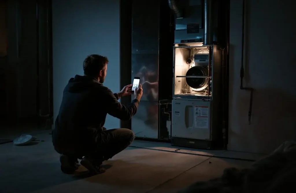
Photograph the LED or display before removing the blower door. Trane tells technicians to disconnect power first, wait 10 seconds for the IFC supply to discharge, and not to bypass the door switch by any permanent means. No Trane LED guide we read describes a stored flash history, so a lost pattern may return only with the fault.
On S8 and S9 displays, press Menu until L6F (last 6 faults), then Option to read. Holding Option for 5 seconds there clears the history; holding Menu and Option for 15 seconds restores factory defaults and erases airflow setup. Trane warns to touch only Menu and Option during fault code recovery. Lockout resets: how to reset a furnace.
Which Trane codes can an owner check, and which mean shut the gas?
Owners can check the filter, registers, vent terminations and condensate drain. E04 or 4 flashes points at airflow and the limit switch; E3.2, E09 or 3 flashes at the vent, trap and pressure switch. S8 and S9 boards lock out for one hour after 3 retries or 10 recycles; after a storm, use the power outage checklist.
Stop for E05, E7.1, 5 flashes on green and red boards, 1 or 10 flashes on three-LED boards, or any gas smell: gas or flame where none belongs. Trane says to shut gas at the manual valve on the supply piping after electrical, fuel or mechanical failures. E6.1, E6.2 and 6 flashes are line voltage: the IFC is polarity sensitive and the hot leg lands on the BLACK lead. See our furnace control board guide; Carrier and Goodman number flashes differently.
Frequently asked questions
What does Trane furnace code 3 mean?
Three red flashes means a pressure switch fault on Trane’s single LED and green and red boards, and a 1st stage pressure switch stuck open on the three-LED board. On S8 and S9 display boards every E3 code is a pressure switch: E3.1 and E3.3 shorted, E3.2 and E3.4 open, per Trane guide 18-CE12D1.
Why is my Trane furnace blinking red light continuously?
A steady red LED is a board fault in every Trane table we read. The single LED table says continuous on means replace IFC; green and red boards with both LEDs on mean internal control failure; a solid red on three-LED boards is an internal gas valve, micro and frequency check error. A technician checks 24 volts and the fuse first.
How do I clean the flame sensor on a Trane furnace?
The Trane guides we read give the target, not a cleaning method: typical flame current of 0.75 to 3.0 micro-amps, where 1 VDC equals 1 micro-amp at the FP pads. Shut power and gas first; our flame sensor guide covers removal and cleaning. If E08 returns, a technician checks ground and flame.
How we researched this
On 6 November 2026 we read 11 Trane eLibrary documents: installer guides 18-CE12D1, 18-CE16D1, 18-CE03D1 and 18-CE15D1, and service installer guides 18-CH52D1, 18-CH49D1, 18-CH92D1, 18-CH111D1, 18-CH76D1, 18-CH61D1 and X341956P04, checking every row against the page image. Repair-site charts were excluded; several contradict Trane. No Trane alarm table for S9V2 or L8V1 was found.
Sources
- Trane. “Installer’s Guide 18-CE12D1-1D-EN (S9X1, S9X2, S9B1).” https://elibrary.tranetechnologies.com/public/residential-hvac/Literature/Installation/18-CE12D1-1D-EN_09162020.pdf. Accessed November 2026.
- Trane. “Installer’s Guide 18-CE16D1-1C-EN (S8B1, S8X1, S8X2).” https://elibrary.tranetechnologies.com/public/residential-hvac/Literature/Installation/18-CE16D1-1C-EN_05052021.pdf. Accessed November 2026.
- Trane. “Installer’s Guide 18-CE03D1-1F-EN (S9V2).” https://elibrary.tranetechnologies.com/public/residential-hvac/Literature/Installation/18-CE03D1-1F-EN_05132020.pdf. Accessed November 2026.
- Trane. “Installer’s Guide 18-CE15D1-1C-EN (L8V1).” https://elibrary.tranetechnologies.com/public/residential-hvac/Literature/Installation/18-CE15D1-1C-EN_04042022.pdf. Accessed November 2026.
- Trane. “Service Installer’s Guide 18-CH52D1-1.” https://elibrary.tranetechnologies.com/public/trane-history/Literature/Installation/18-CH52D1-1_11012009. Accessed November 2026.
- Trane. “Service Installer’s Guide 18-CH92D1-1A-EN.” https://elibrary.tranetechnologies.com/public/trane-history/Literature/Installation/18-CH92D1-1A-EN_07062020. Accessed November 2026.
- Trane. “Service Installer’s Guide 18-CH111D1-1A-EN.” https://elibrary.tranetechnologies.com/public/residential-hvac/Literature/Installation/18-CH111D1-1A-EN_12262023.pdf. Accessed November 2026.
- Trane. “Service Installer’s Guide 18-CH76D1-1A-EN.” https://elibrary.tranetechnologies.com/public/trane-history/Literature/Installation/18-CH76D1-1A-EN_07062020. Accessed November 2026.
- Trane. “Service Installer’s Guide 18-CH61D1-4A-EN.” https://elibrary.tranetechnologies.com/public/trane-history/Literature/Installation/18-CH61D1-4A-EN_07062020. Accessed November 2026.
- Trane. “Service Installer’s Guide X341956P04.” https://elibrary.tranetechnologies.com/public/trane-history/Literature/Installation/X341956P04_03012012. Accessed November 2026.
Leave a Reply