
Oil burner nozzle replacement means fitting a new nozzle with the exact flow (GPH at 100 psi), spray angle and pattern on the appliance spec, at every annual service, never cleaning the old one. Then the electrodes are reset (Beckett AFG: 5/32 in gap) and the burner is retuned with a combustion analyzer.
The nozzle is the brass part at the end of the oil line inside the air tube. The pump forces No. 2 oil through it, and it both atomizes the oil into a cone the spark can light and meters how many gallons per hour the appliance burns. If the burner is locking out right now, start with our oil burner reset button guide.
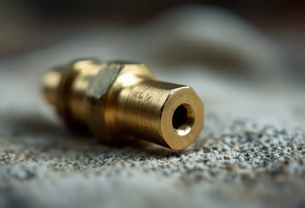
What do the numbers and letter stamped on an oil burner nozzle mean?
A stamp such as 0.85 x 60° B gives three things: flow in US gallons per hour, spray angle in degrees, and spray pattern. Beckett’s AFG manual states that “Nozzle manufacturers calibrate nozzle flow rates at 100 psig.”
| Stamp field | What the maker says it means | What goes wrong if it is not matched |
|---|---|---|
| Flow, e.g. 0.85 | US gallons per hour of No. 2 oil at 100 psi (Delavan, Beckett) | Beckett: under-firing or over-firing, sooting, puff-back |
| Angle, e.g. 60° | Cone angle, 30° through 90° (Delavan) | Beckett: wider angle, shorter flame; the wrong length can impinge on the chamber |
| Pattern, Delavan | A hollow cone (red vial), B solid cone (royal blue vial), W “neither truly hollow nor solid” (green vial) | Delavan: some burners give delayed ignition with a hollow cone spray |
| Pattern, Danfoss | H hollow, S solid, B semi-solid; North American types AH, AS, AB | Danfoss cross reference: Delavan A to H, Delavan B to S, Delavan W to B |
Compiled by The HVAC Brief from the Delavan, Danfoss and Beckett AF/AFG documents listed in Sources.
Why does a 0.85 GPH nozzle burn 1.01 gallons an hour on most burners?
Because the pump runs above 100 psi, and flow rises with the square root of pressure. Beckett’s manual gives the example “A 1.00 gph nozzle at 140 psig = 1.18 gph”, and Delavan warns that “If pressure isn’t carefully checked, the marking on the nozzle becomes meaningless.” The Riello 40 F3 and F5 list 130 to 200 psig, so the real firing rate sits above the stamp.
We checked two makers’ setup charts against that law: flow equals stamped GPH times the square root of psi/100, and input uses Delavan’s sizing constant of 140,000 Btu per gallon (EIA lists 138,500, about 1% lower).
| Appliance or chart | Nozzle (GPH at 100 psi) | Pump psi | Calculated GPH | Maker’s listed firing rate | Input at 140,000 Btu/gal |
|---|---|---|---|---|---|
| Weil-McLain UO-3 CV, Beckett AFG | 0.85 | 140 | 1.006 | 1.00 | 140,803 Btu/h |
| Weil-McLain UO-4 CV, Beckett AFG | 1.00 | 140 | 1.183 | 1.20 | 165,650 Btu/h |
| Weil-McLain UO-5 CV, Beckett AFG | 1.10 | 160 | 1.391 | 1.40 | 194,796 Btu/h |
| Riello 40 F3 chart | 0.75 | 160 | 0.949 | 0.95 | 132,816 Btu/h |
| Riello 40 F5 chart | 1.35 | 145 | 1.626 | 1.65 | 227,586 Btu/h |
HVAC Brief calculation: GPH x √(psi/100), using Weil-McLain Ultra Oil Table 2 and the Riello 40 F3/F5 setup charts. Every row falls inside Riello’s own “5% ±” tolerance.
So a nozzle one size up, or a pump turned from 140 to 175 psi, changes the input as surely as a bigger burner. A 0.75 nozzle at 140 psi delivers 0.89 GPH (Beckett and Delavan agree), about 124,600 Btu/h, not the 105,000 Btu/h the stamp suggests. That is why our heating oil usage figures depend on the actual firing rate, not the nozzle label.
Which nozzle does my burner need, and can I use a different brand?
The one the appliance maker lists for that boiler or furnace, usually on the burner label or in the appliance manual. Beckett is strict: “Use only nozzles having the brand, flow rate (gph), spray angle and pattern specified by the appliance manufacturer”. Weil-McLain’s Ultra Oil table even names brands: 0.85 x 60° B Delavan, or Hago, for the UO-3 CV.
Riello’s retrofit manual is looser, allowing “any approved oil burner nozzle type, angle and manufacturer” if the gph input matches, yet adds “OEM specifications take priority.” With no spec at all, Delavan sizes by GPH = Btu input ÷ 140,000, and Beckett says to fire a mid range angle and switch hollow or solid only if combustion results are poor: a tuning decision made with instruments.
Why is the nozzle replaced at every service instead of cleaned?
Because cleaning cannot be verified and costs more than a new part. Delavan, which flow tests every nozzle at 100 psi, says “most service organizations have shown the best, most economical results can be obtained by replacing nozzles annually” and that disassembly voids the warranty; Danfoss writes that “The best result is obtained when the nozzle is replaced once a year.”
The orifice “is polished to a glasslike finish”, Delavan adds, so no wire, pin or breath to clear it. Small nozzles plug first, which is why Beckett suggests a secondary filter of at least 10 microns below 0.75 GPH. The nozzle change belongs to the same annual visit as the filter change in our boiler service checklist.
How is an oil burner nozzle replacement done on a Beckett AFG, step by step?
Power off, pull the nozzle line, swap the nozzle with two open end wrenches, reset the electrodes, retune. This condenses the Beckett AF/AFG manual and Delavan’s handling rules; a Riello 40 slides out a “drawer assembly” instead.
- Turn off power (there may be 2 disconnects) and close the oil valve.
- Disconnect the oil connector tube, release the 2 igniter clips and tilt the igniter back.
- Remove the splined nut and pull the nozzle line assembly without bending the electrodes (L1, L2, V1 heads: slide forward, rotate 90°, pull).
- Hold the adapter with a 3/4 in open end wrench and remove the old nozzle with a 5/8 in wrench. Compare its stamp with the appliance spec.
- Flush the nozzle line and adapter: Delavan calls for “at least a pint of oil pumped through it”, or compressed air, before a new nozzle goes in.
- Hold the new nozzle by the hex flats, finger tighten, then torque to 90 inch pounds.
- Set the electrodes (next section), reinstall, and check the F head Z dimension: 1-1/8 in from nozzle face to head.
- Fit a pressure gauge, fire the burner and run the combustion test below.
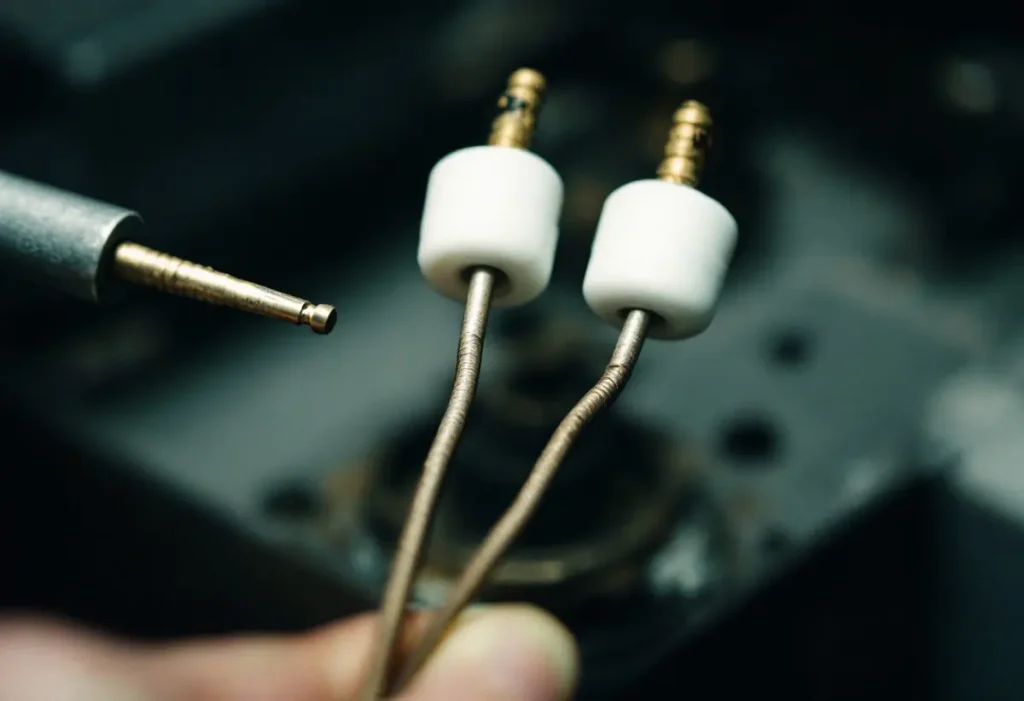
What electrode gap and position go back after the nozzle change?
On a Beckett AFG with an F, L1 or V1 head: a 5/32 in gap between the tips, tips 1/16 in ahead of the nozzle face and 5/16 in above its centerline. Beckett’s annual list adds “Replace electrodes if tips are rounded”, and Delavan’s delayed ignition checklist starts with the electrode setting and cracked insulators.
| Burner | Tip gap | Tips ahead of nozzle | Tips above center | Pump pressure | Nozzle angles |
|---|---|---|---|---|---|
| Beckett AFG, F, L1 or V1 head | 5/32 in | 1/16 in | 5/16 in | Per appliance maker (140 or 160 psig on Weil-McLain Ultra Oil) | F: 70° or 80°; L1, V1: 45°, 60° or 70° |
| Beckett AFG, L2 head and M series ending in N | 5/32 in | 1/8 in | 1/4 in | Per appliance maker | 45°, 60° or 70° |
| Riello 40 F3 and F5 (retrofit) | 5/32 in (4 mm) | 5/64 to 7/64 in (2 to 2.5 mm) | 13/64 in (5 mm) | 130 to 200 psig; chart values 145 to 160 | 60° or 80° in the setup charts |
Compiled by The HVAC Brief from the Beckett AF/AFG manual (Figure 3, Tables 2 and 6) and the Riello 40 F3/F5 manual. Riello prints 7/64 in as 2.5 mm; it is about 2.8 mm.
Why must a combustion test follow every oil burner nozzle replacement?
Because a new nozzle changes droplet size and the real firing rate, so last year’s air setting no longer fits. Beckett’s manual says operation and adjustment “requires technical training and skillful use of combustion test instruments”, and Delavan recommends a pressure gauge, vacuum gauge and “a complete combustion analyzer including a hand held smoke pump tester.”
Beckett’s AFG sequence: run the burner 5 to 10 minutes; set over-fire draft to the appliance spec (natural draft appliances typically -0.01 or -0.02 in. w.c.); close the air until a trace of smoke appears and read CO2 or O2 there (example 13.5% CO2); then add air until CO2 drops 1.5 to 2 points, for example from 13.5% to 11.5%; confirm smoke is zero; then check pump pressure, cutoff and lockout timing. Skipping the analyzer is how soot and an oil furnace puffback happen.
The stop line for homeowners: Beckett tells owners to “Contact a professional, qualified service agency for installation, start-up or service work”, and in many jurisdictions oil burner work is licensed. Ask the technician for the printed results: nozzle stamp, pump psi, draft, smoke number, CO2 or O2 and stack temperature.
How do you know an oil burner nozzle is bad?
By the flame and the start, not by looking at it. Delavan lists “A partially plugged nozzle causing off-center spray” as a cause of delayed ignition (a start with a puff), says a clogged nozzle can make a spray “impossible to ignite”, and that back pressure overheats nozzles into coke. These show up as lockouts, soot or odors; our page on a heating oil smell in the house sorts the smell cases.
Low pressure mimics a worn nozzle: Delavan notes clogged filters cut pressure between pump and chamber, so the gauge reading separates nozzle from supply faults. How the nozzle fits into the rest of the system is in our oil heating system explainer.
Frequently asked questions
How much does oil burner nozzle replacement cost?
We publish no dollar figure because no federal or national laboratory source reports one. The nozzle is normally changed inside the 1 annual service, not billed as a separate repair: Beckett’s checklist pairs it with the line filter, pump strainer, electrodes and a combustion test, and Delavan calls annual replacement the most economical practice.
What wrench do you use for an oil burner nozzle?
On a Beckett AF or AFG, the manual calls for a 3/4 in open end wrench on the nozzle adapter and a 5/8 in open end wrench on the nozzle, finger tight first and then 90 inch pounds. Dedicated nozzle wrenches do the same job; Delavan warns that bumping the orifice with a wrench can streak the spray.
Where is an oil burner nozzle size chart?
The useful chart is flow at pump pressure, in Beckett’s AFG Table 5 and Delavan’s pressure table: a 0.75 nozzle flows 0.89 GPH at 140 psi, and a 1.00 nozzle flows 1.18 GPH at 140 psi and 1.41 GPH at 200 psi. Your size is on the burner label or in the appliance manual.
Is oil furnace nozzle replacement different from an oil boiler?
No. The same flame retention burners are fitted to both: Riello’s 40 F3/F5 manual starts nozzle selection with the firing rate “for the boiler or furnace units”, and Delavan’s sizing rules cover hot water and warm air heat alike. The swap, electrode settings and combustion test are identical; only the specified nozzle differs.
How we researched this
On 21 November 2026 we read the 6 documents in Sources (Delavan pages via archived copies, as the live site blocks automated readers) and ran the flow law against the makers’ setup charts with a short script. We excluded contractor blogs, retail listings, forums and videos as sources for figures, and publish no installed price because no federal or laboratory source reports one. Related upkeep is in our furnace maintenance checklist.
Sources
- R.W. Beckett / Weil-McLain. “Beckett Model AF/AFG Burners Instruction Manual (Ultra Oil).” https://www.weil-mclain.com/wp-content/uploads/RW-Beckett-AFG-Burner-Manual-for-Ultra-Oil-VBL-0321.pdf. Accessed November 2026.
- Riello / Weil-McLain. “Riello 40 Series Models 40 F3 & F5 Installation & Operating Manual.” https://www.weil-mclain.com/wp-content/uploads/wgo-riello-oil-burner-manual_1.pdf. Accessed November 2026.
- Delavan. “A Total Look at Oil Burner Nozzles” (archived copy). https://web.archive.org/web/2025id_/https://delavan.com/wp-content/uploads/2022/06/Delavan-Total-Look-Book.pdf. Accessed November 2026.
- Delavan. “Care and Service Tips for Oil Burner Nozzles” (archived copy). https://web.archive.org/web/2025id_/https://delavan.com/care-and-service-tips-for-oil-burner-nozzles/. Accessed November 2026.
- Danfoss. “Oil Nozzles for your service.” https://assets.danfoss.com/documents/94533/AD135386457088en-010101.pdf. Accessed November 2026.
- U.S. Energy Information Administration. “British thermal units (Btu).” https://www.eia.gov/energyexplained/units-and-calculators/british-thermal-units.php. Accessed November 2026.
Leave a Reply